VLAN Example 01
 |
| VLAN Example 01 |
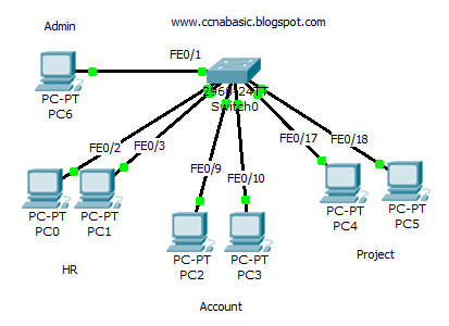
Port 0/1 For admin PC 192.168.0.1/27
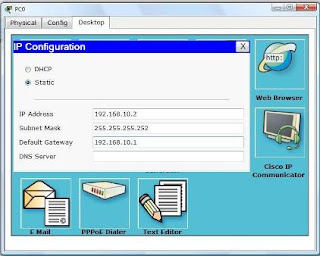
Port 0/2 to 0/8 for HR division. 192.168.0.2 to 8/27
Port 0/9 to 0/16 for Accounts division. 192.168.0.9 to 16/27
Port 0/17 to 0/24 for Project division. 192.168.0.17 to 24/27
Check the configuration very carefully and try yourself. If you fail just download the given file and correct. Download: Simple VLAN.pkt
Switch#
Switch#enable
Switch#configure terminal
Switch(config)#vlan 2
Switch(config-vlan)#name HR
Switch(config-vlan)#exit
Switch(config)#vlan 3
Switch(config-vlan)#name Account
Switch(config-vlan)#exit
Switch(config)#vlan 4
Switch(config-vlan)#name Project
Switch(config-vlan)#exit
Switch(config)#interface f0/1
Switch(config-if)#switchport mode access
Switch(config-if)#switchport access vlan 1
Switch(config-if)#exit
Switch(config)#interface range f0/2-8
Switch(config-if-range)#switchport mode access
Switch(config-if-range)#switchport access vlan 2
Switch(config-if-range)#exit
Switch(config)#interface range f0/9-16
Switch(config-if-range)#switchport mode access
Switch(config-if-range)#switchport access vlan 3
Switch(config-if-range)#exit
Switch(config)#interface range f0/17-24
Switch(config-if-range)#switchport mode access
Switch(config-if-range)#switchport access vlan 4
Switch(config-if-range)#exit
Switch(config)#exi
Switch(config)#exit
Switch#


Comments
Post a Comment